BIOCOS ® wastewater treatment plants
K.
Ingerle
1. Introduction and short system
description
2. Operation scheme
3. Comparison of the Biocos
strategy with the continuous activated sludge process
4. 4-phase end 3-phase BIOCOS
strategy
5. Continuous flow and cyclic flow
systems
6. 4-phase BIOCOS strategy for large
WWTPs (continuous flow)
7. 3-phase BIOCOS strategy for small
WWTPSs (cyclic flow)
8. Economic and technical
efficiency
1. Introduction and short system description
The
Biocos-strategy (biological combined system) represents an advancement of the conventional activated
sludge system. Main differences concern the sludge-water-separation and the
sludge recycle.
The
development of the Biocos-strategy was based on the intention to avoid
disadvantages of the secondary clarification and the sludge recycle. The
secondary clarifier usually provides the separation of sludge and supernatant
water as a exclusively physical process. The clarifier is operated at a low
sludge blanket level and therefore low sludge mass. Degradation processes in
the clarifier are not relevant and must not be considered in the plant design.
The clarifier volume required for sedimentation is designed for storm water
flow. In case of a combined sewer system the ratio between dry weather rain
weather flow is in the range of 1:4 and consequently the degree of utilisation
is 25 % most of the time. This fact is economically insufficient and can cause
troubles with frost during winter time. Another disadvantage are current and
short circuit effects in the secondary clarifier. Continuously the mixed liquor
from the aerated reactor is fed to the clarifier, the supernatant water
discharged and the return sludge recycled and these complex flow pattern can
influence the sedimentation process and lead to the wash out of sludge flocs. A
reduces treatment efficiency is the consequence. Finally an additional cost
intensive construction is required – the pumping station for the return sludge
cycle.
The
Biocos-strategy tries to avoid the mentioned disadvantages. Wastewater is fed
to an aerated reactor (B-reactor) and from there to a sedimentation and
circulation reactor (SU-reactor). Several operation cycles are conducted every
day with a recycle period (sludge recycle phase "S") and a stirring
period when the settled sludge in the SU-reactor is mixed with the supernatant
water (mixing phase "U"). Afterwards the sludge in the SU-reactor
settles (settling phase "V") and finally supernatant water is
withdrawn (discharge phase "A"). The B-reactor and the SU-reactor are
hydraulically connected near the bottom in order to grant efficient sludge
recycling.
2. Operation scheme
An operation cycle of the Biocos-strategy
is usually divided into 4 phases (S,U,V and A). Therefore this system is
addressed as the 4-phase Biocos-strategy. Biocos-WWTPs for municipal wastewater
are adjusted to 10 to 14 operation cycles a day in most cases.
During the S-phase (sludge recycle) well thickened
sludge is pumped from the bottom of the SU-reactor to the B-reactor. At the
same time the displaced content of the B-reactor flows via the connection near
the bottom to the SU-reactor. Since both reactors are hydraulically connected
with nearly the same water level, only a small amount of energy is required. A
siphon operated with pressed air is an proved facility for sludge recycling.
During the U-phase (mixing phase) the sludge in
the SU-reactor is stirred for a few minutes until a homogeneous content of this
reactor is achieved. At the end of the U-phase the sludge concentration in the
B-reactor is significantly higher than in the SU-reactor. The high biomass
content in the B-reactor promotes the biochemical processes whereas a low
suspended solids concentration in the SU-reactor accelerates the sedimentation
process (see chapter 6.6).
During the V-phase (settling phase) the sludge
settles after a short period of subsiding turbulence and starting flocculation
in the SU-reactor. A horizontal sludge blanket develops and settles at a nearly
constant velocity vs. According to ATV A210 the settling velocity is
calculated as follows vs [m/h] = 650 / (SVI [ml/g l] x SS [g/l]).
The slowly settling sludge body operates like a floc filter which filtrates
also small particles out of the supernatant water and guarantees a solid free
effluent quality. This effect reduces not only the COD-concentration but also is
a precondition for disinfection measures (e.g. UV-treatment) if required.
During the A-phase (discharge phase) supernatant
water is withdrawn from the SU-reactor while the sludge blanket continues
settling. The content of the B-reactor flows to the SU-reactor via a connection
near the bottom entering the layer of settling sludge. Discharge facilities are
locates at the opposite side of the SU-Reactor in order to avoid a short
circuit from the influent to the effluent flow.
During each of
the 4 operation periods relevant biochemical
processes occur in the SU-reactor. As long as nitrate or nitrite is
available endogenous denitrification is the main process. The biomass itself is
the main carbon source for denitrification. A smaller part of the carbon supply
is taken from the soluble fraction (hardly degradable organic matter) causing a
decrease of the COD effluent concentration. After a complete reduction of the
oxidised nitrogen an advanced biological P-elimination is promoted.
3. Comparison of the BIOCOS strategy with the continuous activated sludge process
The objectives
of the processes in the SU-reactor are summarised in following tasks:
·
Sludge-water-separation
·
Recycling of the sludge shifted from
the B-reactor to the SU-reactor
·
Cyclic development of a floc-filter in
order to achieve a solid-free effluent and a decrease of the COD-effluent
concentration
·
Utilisation of the reactor volume for
biochemical processes – mainly N-elimination by endogenous denitrification,
organic degradation and partly biological P-elimination
|
Biocos-strategy SU-reactor |
Continuous flow activated sludge system secondary clarifier + RS-pumping station |
|
sludge-water-separation |
sludge-water-separation |
|
discharge of supernatant water |
discharge of supernatant water |
|
sludge recycling |
sludge recycling |
|
development of a floc-filter |
----- |
|
biochemical processes |
---- |
4. Four-phase and three-phase BIOCOS strategy
Following the
4-phase Biocos-strategy (S-, U-, V- and A-phase) the S- and the U-phase are
performed consecutively. Both phase require separate facilities. This leads to
a higher sludge concentration in the B-reactor than in the SU-reactor. In
chapter 2 each phase was described.
Fig.1: 4-phase strategy
According to the 3-phase Biocos strategy
the S-phase and the U-phase are joined in one circulation phase (U-phase).
Sludge recycling, stirring and homogenisation takes place at the same time by
the same equipment. This operation achieves nearly the same sludge
concentration in the B- and in the SU-reactor.
Fig.2: 3-phase strategy
Considering the 4-phase strategy eventually developed floating sludge in the
SU-reactor is integrated into the activated sludge during the U-phase. During
the U-phase of the 3-phase process the recycle flow transports the floating
sludge to the B-reactor where it is integrated or separated.
5. Continuous flow and cyclic flow systems
5.1 Continuous flow system
If the
influent flow of a WWTP is equal to the effluent flow than a continuous flow
strategy has been applied. Since supernatant water can be discharged from the
SU-reactor during the A- (discharge) phase, each B-reactor has to be assigned
to at least 2 SU-reactors. In this case at any time the influent flow fed to
the B-reactor displaces the supernatant water via the open effluent valves of
one SU-reactor. Considering two SU-reactors the phase intervals have to fit following
condition: S + U + V = A (4-phase cycle)
Fig.3: Plot
Fig.4: 4
phases of a Biocos operation cycle
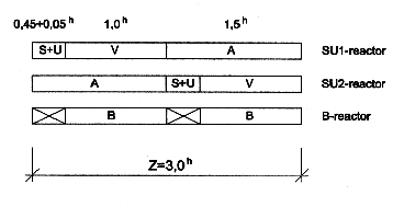
During the S-,
U- and V-phase neither influent nor effluent flow occurs in the SU-reactor. For
about one hour during the V-phase the sludge settles without any hydraulic
disturbances. The flow in the SU-reactor is controlled by the effluent valve.
An almost constant water-level is achieved by a fixed weir.
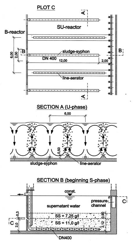
Fig.5: Section
of the discharge equipment
From the
economical point of view it is appropriate to interrupt the aeration of the
B-reactor and to use the pressed air to operate the S- and the U-phase. The
continuous flow Biocos-strategy can also be operated in a 3-phase cycle.
5.1 Cyclic flow system
If only one
SU-reactor is assigned to the B-reactor then the water-level varies. The
disadvantage of this flow scheme is a transient loading of the receiving water.
An additional storage tank can equalise the cyclic discharge flow.
Another aspect
of a cyclic flow is the large amount of mixed liquor shifted from the B- to the
SU-reactor (QSU). The hydraulic design needs to consider this load
in order to prevent a wash-out of solids. Therefore this system seems to be
more suitable for separate sewer systems and small WWTPs.
Assuming that
the influent flow Qin and the effluent flow Qef are
constant and the discharge phase has a duration of A [h], then
QSU [m3/h] = Qin [m3/h] + Vstorage
B [m3] : A [h] .... (1)
Qef [m3/h] = Qin
[m3/h] + (Vstorage B [m3] + Vstorage SU
[m3]) : A [h] .... (2)
Fig.6: Section
of the Biocos reactors
6. Four-phase BIOCOS strategy for large WWTPs (continuous flow)
6.1 Description of the strategy
The
description of a design example for a large WWTP of 1.0 million pe should
deepen the understanding of the Biocos-strategy. The municipal wastewater from
a combined sewer system of a large city is assumed to be fed to a Biocos-plant
after pre-clarification. The P-elimination is mainly achieved by precipitation.
The Biocos-plant consists out of 10 lines, each line comprises one B-reactor
and two SU-reactors.
Wastewater is
fed to a generously designed middle
channel where a almost horizontal water table occurs because of only small
energy head losses. To prevent settling of suspended solids the middle channel
is intermittently aerated and stirred.
The wastewater
from the middle channel is led via valves and weirs to the B-reactors of the 10 Biocos lines. The B-reactors are designed as
oxidation ditches and equipped with fine-bubble aeration stirrers. During
V-phases the B-reactors are aerated and nitrification and aerobic organic
degradation is promoted. During the S- and U-phases aeration is interrupted
aiming on pre-denitrification. Control periods of the phases as presented in
Fig.4 result in following biochemical coefficients regarding the B-reactors:
zB,aerob = 2.0
: 3.0 = 0.67
zB,anox = 1.0
: 3.0 = 0.33
After the effluent valve is opened supernatant water is
discharged from the SU-reactor during the A-phase. In the same time
biologically treated wastewater-sludge mixed liquor flows through apertures
near the bottom from the B- to the SU-reactors. Relatively high energy head
losses within the discharge facilities are adapted in order to achieve a
constant line-discharge. The return flow of the sludge which has been displaced
from the B- to the SU-reactor during the A-phase happens discontinuouslv during
the S-phase. After a thickening period of about 2.5 hours well thickened
activated sludge is recycled to the B-reactor by siphons. The siphons are run
by pressed air which is available from the interrupted aeration system.
The stirring equipment is also run by pressed air and mixes
the content of the SU-reactor (U-phase) including floating sludge. During the
U-phase the aeration system is still interrupted and pressed air is provided
for stirring. Afterwards the pre-settling phase (V-phase) starts. A short
flocculation period of about 0.1 h precedes the actual sedimentation of the
sludge blanket with the constant settling velocity vs. According to ATV M210
the settling velocity is calculated by following equation:
vs = 650 :
(SVI x SSSU)
At the beginning of the discharge period (A-phase) the
sludge blanket should have settled at least 50 cm and this clarification zone
should stay stable while discharging. The settling sludge body serves as a
flocculation filter adsorbing suspended and floating solids and improving the
effluent water quality. In the Su-reactor permanent endogenous denitrification
takes place as long as NO3 is available. The rates of endogenous
denitrification reach values of at least 25 % of the pre-denitrification rates.
Fig.7:
Presentation of the S-, U-, V- and A-phase
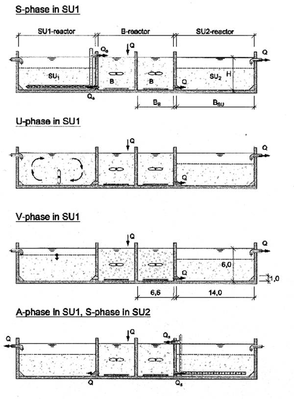
Fig.8: 10-line Biocos-WWTP designed fot 1.0
million pe
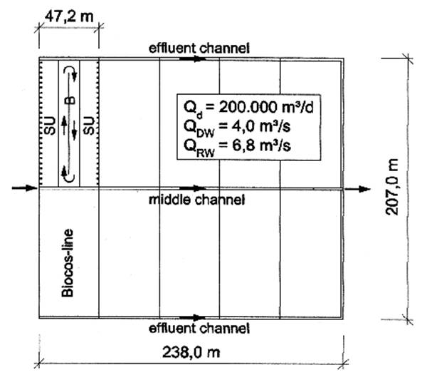
Supernatant
water discharged from the SU-reactors is fed to the effluent channel and further on to the receiving water. The Biocos-lines are operated in parallel
phases. This concept results in a simple control system and a clear survey of
the operator. Waste-sludge withdrawal
is performed automatically at the beginning of the S-phase. If necessary state
of the art devices for floating sludge
separation should be installed in the B-reactors but not in the
SU-reactors.
The amount Vs,DW of thickened sludge which should be recycled from
the SU-reactor to the B-reactor during dry weather flow determines the mean
suspended solids concentration and consequently the volume of the B-reactor.
When the influent flow exceeds the dry weather flow QDW the amount
of recycled sludge VS,RW is automatically switched to storm weather
conditions. Obviously the total sludge mass in the system needs to be
considered.
Computer calculations and full-scale experiments at a 10.000 p.e. Biocos-plant
have shown that at a constant amount of recycled sludge VS,DW
variations of suspended solids concentrations in B- and SU-reactors due to
influent flow variations is relatively small because of the large total sludge
mass SMtot. The calculation approach in chapter 6 results SS-values
of satisfying accuracy.
6.2 Characteristic design values of the reactors
Experiences
from full-scale applications indicate the optimum range of two design
parameters:
· Depth
H of the reactors of large Biocos-plants should not undershoot 5.0 m.
Preferable is a depth of 6.0 m.
· Width
BSU of the SU-reactors should be in the range between 12.0 and 14.0
m in order to optimise the required energy input for stirring.
Further design
parameters of the SU-reactor have to agree with the hydraulic and of the
B-reactor with the biochemical design calculations.
6.3 Load parameters
Hydraulic
parameters
|
Specific wastewater flow: |
Q = |
200 |
l/pe |
|
Daily hydraulic load: |
Qd = |
0.2 x pe |
[m3/d] |
|
Mean dry weather flow: |
Qm = |
0.2 x pe : 24 |
[m3/h] |
|
Max. dry weather flow: |
QDW = |
0.2 x pe : 14 |
[m3/h] |
|
Max. storm weather flow: |
QRW = |
QDW x 1.7 |
[m3/h] |
Organic
load and biological parameters
Parameter
estimation according to ATV A131 and ATV M210 (P-precipitation)
· 40
g BOD/pe (organic loading of the biological stage)
· 11
g Ntot./pe (total nitrogen load)
· Aerobic
sludge retention time: tSS,aerob = 8 d
· Waste
sludge: WS = 1.2 kg SS/kg BOD
· Sludge
volume index: SVI = 100 ml/g
· Thickened
sludge: SSe = (12.5 + 9.5) : 2 = 11 g/l (average)
· Sludge
settling velocity in the SU-reactor vs = 650 : (SSSU x
SVI) [m/h]
· Flocculation
period: 0.1 h
· Pre-denitrification:
DN-rate = 20 g NO3-N/kg SS.d
· Endogenous
denitrification: DN-rate = 5 g NO3-N/kg SS.d
6.4 Hydraulic calculation (1000 pe)
Stormwater
flow QRW is relevant for the calculation of the required surface
area of the SU-reactors. The assumed width of the SU-reactors is BSU
= 14.0 m and the depth H = 6.0 m. A 1000 pe plant would require a strip of 1.0
m length and a 1.0 Mill. pe plant 10 lines with 100.0 m length (Fig.10):
FSU,requ
x [ vs (Z – S – U – 0.1) – 0.5] = QRW . A
QDW = 1000 x 0.2 : 14 = 14.3 m3/h ; QRW = 24.3 m3/h; Qm
= 8.3 m3/h
vs = 650 : (100 x 5.0) = 1.3 m/h (SSSU = 5.0 g/l assumed)
FSU,requ. = 24.3 x 1.5 : (1.3 x 2.4 – 0.5) = 13.9 m2
L = 13.9 : 14.0 = 1.0 m
VSU = 14.0 x 1.0 x 6.0 = 84.0 m3
6.5 Biochemical calculation (1000 pe)
The mean dry
weather flow determines the required volume of the B-reactor. The recycled
amount of sludge VS,DW of 24.0 m3 is assumed and the available
amount of thickened sludge in the SU-reactor until the S-phase needs to be
proven:
The simplified
equation for sludge displacement
(SSe – SSB) x VS,DW
= SSB x Qm x A
results in the
mean suspended solids concentration in the B-reactor
SSB = 24.0 x 11.0 : (24.0 +
8.3 x 1.5) = 7.25 g/l.
The required
sludge mass for 1000 pe is
SMaerob,requ. = 1000 x 0.04
x 1.2 x 8 = 384 kg SS
SMaerob,requ = 2 x L x BB x H x zB,aerob x SSB
BB = 384 : (2 x 1.0 x 6.0 x 0.67 x 7.25) = 6.6 m
VB = 2 x 6.6 x 1.0 x 6.0 = 79.2 m3
SMtot. = (VSU + VB) x SS = (84.0 + 79.2) x 5.0 = 816 kg SS
SSSU x VSU + SSB x VB = SMtot.
SSSU = (816 – 7.25 x 79.2) : 84.0 = 2.9 g/l
The sludge
volume of the sludge thickened during the V- and the A-phase (2.5 hours) at dry
weather flow expects values of about:
Sludge body of
11.0 g/l : 6.0 x 3.9 : 11.0 = 2.12 m
Sludge volume with 11.0 g/l: 14.0 x 1.0 x 2.12 = 29.4 m3 > VS,DW
= 24.0 m3
vs = 650 : (100 x 3.9) = 1.66 m/h
This state is achieved after: (6.00 – 2.12) : 1.66 = 2.34 h < 2.5 h
Under the
assumption that the sludge recycled from the SU-reactor to the B-reactor
experiences no further thickening: Qm x A = 8.3 x 1.5 = 12.5 m3 ; SS
= 7.25 g/l
At storm
weather flow (influent flow > QDW) the amount of recycled sludge VS,DW is
increased to VS,RW = 30.4 m3 and consequently at QRW =
24.3 m3/h ; SSB = 30.4 x
11.0 : (30.4 + 24.3 x 1.5) = 5.0 g/l and
SSSU = 5.0 g/l. The most
simple way to increase VS,RW is the prolongation of the S-phase from
0.45 h to 0.45 x 30.4 : 24.0 = 0.57 h. The volume of the thickened sludge is:
Sludge body with 11.0 g/l: 6.0 x 5.0 :
11.0 = 2.73 m
Sludge volume with 11.0 g/l: 14.0 x 1.0 x 2.73 = 38.2 m3 > 30.4 m3
vs = 650 : (100 x 5.0) = 1.3 m/h
This state occurs after: (6.00 – 2.73) : 1.3 = 2.5 h
N-Elimination:
|
|
11.0 kg |
|
|
Biomass uptake: 25 % |
- 2.8 kg |
|
|
DN in B-reactor 2 x 39.6 x 7.25 x 20 x 0.33 = |
- 3.8 kg |
(DNpre.=20gNO3-N/kg SS.h) |
|
DN in SU-reactor 2 x 84.0 x 3.90 x 5 x 1.0 = |
- 3.3 kg |
(DNend.= 5 g NO3-N/kg SS.h) |
|
|
+ 1.1 kg |
|
N-Elimination
(11.0 – 1.1) : 11.0 = 0.90 = 90 %
The presented
project for 1.0 mill. pe is based on approved design parameters of the ATV A131
and M210 which have been applied carefully with reserve capacities. If pilot
tests for a planned treatment plant reveal lower design parameters the size of
the reactors will be reduced according to the changed parameters. For instant
the design of large plants is often based on an aerobic sludge retention time
of 6 days instead of 8 days. In this case BB is reduced from 6.6 m
to 6.6 x 6 : 8 = 5.0 m.
6.6 Suspended solids concentration at dry weather flow
The 4-phase Biocos strategy is especially
suitable for large plant applications and is characterised by a separate sludge
return flow. Two different devices are required, one for sludge recycling and
one for stirring of the SU-reactor. The advantage of a separate recycle flow is
are essentially higher sludge concentrations in the B-reactor than in the
SU-reactor and the flap-apertures at the water surface are not required. Fig.9
shows the SS-concentrations of the 4-phase Biocos plant considered in chapter 5
and 6 (1 Mill. pe) in comparison with SS-concentrations of a 3-phase
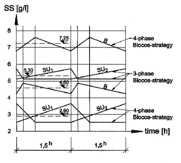
Biocos-plant of the same size. Remarkable is the difference of the
SS-concentration in the B-reactor under dry weather conditions between 3- and
4-phase operation increasing from 4.6 g/l to 7.25 g/l while the concentration
in the SU-reactor drops from 5.3 g/l to 2.9 g/l.
Fig.9: SS-concentration of the 3-phase and the
4-phase Biocos strategy (dry weather flow)
These mass
transports have been calculated by simple computer simulations and investigated
by full-scale pilot tests at the WWTP Längenfeld (Tirol). The measurement data
of the thickened sludge agreed with figure 2 of the ATV A131. The mean
SS-concentration during the total thickening time of 2.5 hours corresponds to
the value for 1.25 h of the thickening profile.
6.7 Operational equipment of the Biocos-plant
Middle
channel
To avoid
sedimentation in the middle channel aeration devices for short term operation
should be installed. Additionally 10 plain slide valves are required in order
to close each Biocos line separately (B / H = 1.0 / 0.7 m). Exact distribution
of the wastewater is managed by 1.0 m wide weirs, which can also be closed for
maintenance.
B-reactor
The B-reactors
are constructed as state of the art oxidation ditches. A stirring device to
induce the cycling current with a velocity of v = 0.5 m/s and a fine-bubble
aeration is installed. The oxygen input is controlled by oxygen probes. In case
of flotation sludge occurrence an approved separator is suggested. Continuous
hydraulic connections between the B- and the SU-reactor are ensured by
apertures without valves.
SU-reactor
Supernatant
water is withdrawn from the SU-reactor (A-phase) by discharge devices with
gravity driven balls. The devices are installed every meter and have been
approved during the last 5 years at several treatment plants. At maximum
hydraulic load the energy head losses within the discharge devices are about 25
cm causing an exact distribution of the effluent flow (line-discharge). The
discharged water is fed to a generously designed pressure pipe with very low
hydraulic head losses. An automatic plain slide valve (B / H = 0.7 / 1.0 m) at
the end of the pipe keeps the water level in the SU-reactor always constant.
The return
sludge flow from the SU- to the B-reactor (S-phase) is performed by
compressed-air siphons (S-siphons) which are situated every 6.0 m. The pump
capacity of such a siphon with a diameter of DN 400 mm is QH = (24.0
: 0.45h) x 6.0 = 320 m3/h = 89 l/s. The compressed-air demand is 29 l/s for
each siphon. Compressed-air is not limited during this phase because the
aeration of the B-reactor is interrupted.
The stirring
of the SU-reactor is also driven by compressed-air. The aeration in the
B-reactor is still interrupted during this phase (U-phase). Lines of
coarse-bubble aerators are installed at the bottom of the reactor in distances
of about 6.0 m (Fig.11). Vertical internal cycle currents are induced to mix
the content of the SU-reactor including flotation sludge with a low energy
input. This kind of stirring device is also applied for aerated sand- and
grease traps. The S-siphon and the line-aerators are operated at lower
air-pressure than the aerator in the B-reactor. Therefor the air-supply for the
aerators in the B-reactors need not be closed during the S- and the U-phase.
The
SU-reactors can be divided by concrete walls each 20.0 to 30.0 m in order to
avoid disturbances by wind and eventual transverse flows. The hydraulic
conditions are simple as demonstrated in Fig.10:
Fig.10: Hydraulic profile
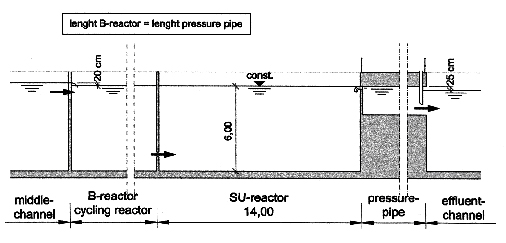
Fig.11:
Plot and sections of the SU-reactor (1.0 Mill. pe)
Compressed-air
supply
The compressed
air demand depends exclusively on the aeration of the B-reactors. When the
aeration is interrupted the provided compressed-air is sufficient for the
operation of the S- and the U-phase. Each Biocos line employs 5 electronic
valves to direct the air-flow either to the aeration, to the S-siphon or the
U-siphon which are located near the middle channel.
Control
system
The control
system operates the phases of all 10 lines in parallel in order to maintain a
uniform state of the plant. When the influent flow exceeds QDW then
the duration of the S-phase is prolonged from 0.45 h to 0.57 h. A plain slide
valve keeps the water level constant in the SU-reactor during the discharge
period (e.g. Fa KLAWA).
7. Three-phase BIOCOS strategy for small WWTPSs (cyclic flow)
7.1 Description of the strategy
Since a
separate sludge treatment for small WWTPs is not efficient, the sludge should
be transported to the next larger plant for further treatment. In this case a primary settler, which is also used as
a waste sludge storage tank, offers
a good solution. Additionally a primary settler with variable water level can
contribute to the equalisation volume. An appropriate hydraulic connection
between primary settler and Biocos-plant needs to be provided.
In order to
avoid odour nuisance, all reactors should be covered and the collected air
should be pressed into the aeration system of the B-reactor.
Waste sludge
should be withdrawn from the SU-reactor every cycle at the end of the V-phase.
From a level of about 1 m below the water surface a mixture of supernatant
water and activated sludge is pumped to the primary settler for a short
interval. This procedure ensures the maximum amount of biomass in the system in
correspondence with the settleability of the sludge. Another advantage of a
recycle flow between Biocos-plant and primary clarifier is the continuous
displacement of highly concentrated wastewater which means a load equalisation
for the biological stage also during the low loaded night period.
The technical
equipment of such Biocos-treatment plant should be operated by compressed air:
· Compressed
air supply (2 compressors)
· Fine
bubble aeration
· Mixing
unit (operated like a mammoth pump, see chapter 4)
· Discharge
siphon controlled by a float switch
· Waste
sludge withdrawal siphon
· Computer
control for automation
· 2
flap valves
During the
U-phase the mixed liquor from the B-reactor is fed to the SU-reactor near the
bottom at high rate. Displaced water is recycled to the B-reactor via the flap
valves.
The recycled
current carries also eventually developed scum to the B-reactor where it will
be re-integrated by the aeration.
During the U-
and the A-phase (including a 2 min period of waste sludge withdrawal) the
aeration stops and the available compressed air is used to operate the required
facilities for pumping and stirring.
Operation
scheme: U = 10’; V = 60’; max. A = 30’
Average cycle: 70’ + 30’ * 10 / 24 = 82.5’
Aeration factor: z B
= 60’ / 82.5’ = 0.727
7.2 Biocos WWTP-design for 1000 pe
The municipal
wastewater from a separate sewer system (1000 pe) should be treated:
· Biocos-load:
40 g BOD5/pe ; 40 kg BOD5/d (pre-clarified)
· 150
l/pe ; m = 10 ; Qmax = 1000 x 0,15 : 10 = 15 m3/h
· sludge
retention time tSS = 10 Tage ; WS (waste sludge) = 0,9 kg SS/kg BOD5
· SVI
= 150 ml/g l ; SS = 3,5 g/l ; vs = 650 : (150 x 3,5) = 1,25 m/h
· min.
depth H = 3,7 m
· area
of primary clarifier: 2 x 25 = 50 m2
· area
of the Biocos-plant: 28,0 + 47,0 = 75 m2
Hydraulic
design:
· Damming
up during the U- and V-phase: DH =
(70´: 60´) x 15,0 : (50 + 75) = 0,14 m
· Dischargeable
supernatant water (FSU = 28,0 m2):[(90´- 5´) : 60´x 1,25
– 0,70] x 28 = 30,0 m3 > 100´ : 60´ x 15,0 = 25,0 m3
· Effluent
flow: Qef = 25,0 : 0,5 = 50 m3/h = 50 : 3,6 = 13,9 l/s
· Effluent
equalisation tank: Vstorage = 50 x (13,9 – 15,0 : 3,6) : 13,9 = 35,0
m3 ; Fstorage = 35,0 : 3,7 = 9,5 m2
· Effluent
equalisation pump: 15,0 m3/h = 15,0 : 3,6 = 4,2 l/s
· QSU
= 15,0 + (500 + 47,0) x 0,14 : 0,5 = 42,2 m3/h
Biochemical
design:
· Aerobic
biomass (FB = 47,0 m2)
Biomassaerob,requ. = 40 x 0,9 x 10,0 = 360 kg SS
Biomassaerob,act. = 47,0 x 3,7 x 3,5 x 0,727 = 442 kg SS
Fig.12: Plot and section of a Biocos treatment
plant for 1000 pe (cyclic flow)
· N-elimination:
(endogenous DN = 5 g NO3-N/kg SS.d; pre DN = 20 g NO3-N/kg SS.d)
|
total nitrogen: |
+ 11,0 kg/d |
|
in the sludge: |
- 3,0 kg/d |
|
in the B-reactor (pre-DN) 47,0 x 3,7 x 3,5 x 0,273 x 0,020 = |
- 3,2 kg/d |
|
in the SU-reactor (endogenous) 25,0 x 3,7 x 3,5 x 0,005 = |
- 1,6 kg/d |
|
|
+ 3,2 kg/d |
8. Economic and technical efficiency
Continuous
flow without pumping from storage tanks, low energy demand for sludge recycling
from the SU-reactor to the B-reactor, high nitrogen elimination because of
extensive endogenous denitrification during clarification, optimised volume
requirements, low maximum electrical power demand, simple and approved
mechanical equipment and a reliable control system cause low operating costs
and high efficiency.
Various
examples of constructed Biocos-WWTPs in Germany, Austria and other countries
demonstrate the efficiency especially of physical and chemical processes in the
SU-reactor. The settling sludge floc-filter – recomposed every 3 houres – and
endogenous denitrification cause average CSB effluent values around 30 mg/l and
a N-elimination rate of about 90 %.
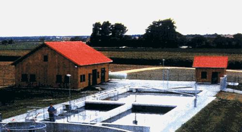
Fig.13:
Picture of a 3-phase Biocos-WWTP with continuous flow operation
References:
Advisory
leaflets ATV-A 131 and ATV-M 210 (in German), German wastewater technique
Association
Ingerle K.: Biocos activated sludge plants, WWTPs Längenfeld and Bielenhofen
(in German), gwf-Abwasser Spezial, 139 (1998), 14
Ingerle K.: Biocos-plants, description and design (in German), Korrespondenz
Abwasser, 1999 (46), Nr. 8
Wett B.: Simulation analyses of a Biocos-plant "cyclic clarification"
or "continuous flow SBR", Korrespondenz Abwasser, 1999 (46), Nr. 7
Wett B., Ingerle K.: Feedforward aeration control of a Biocos-WWTP.; 2nd
Int.Symp. on SBR Techn., Narbonne Wat.Sci.&Tech.43/3, 85-91
Author:
Univ.-Prof.
Dipl.-Ing. Dr.techn.Kurt Ingerle
University of Innsbruck, Institute for Environmental Engineering,
Technikerstr. 13, A-6020 Innsbruck
Tel.: +43 / (0)512 / 507 - 6921
Fax.: +43 / (0)512 / 507 - 2911
E-mail: umwelttechnik@uibk.ac.at
![]()
21. Mai 2001 © Ingerle